MGRE+OSPF实验
创始人
2025-05-29 22:58:34
0次
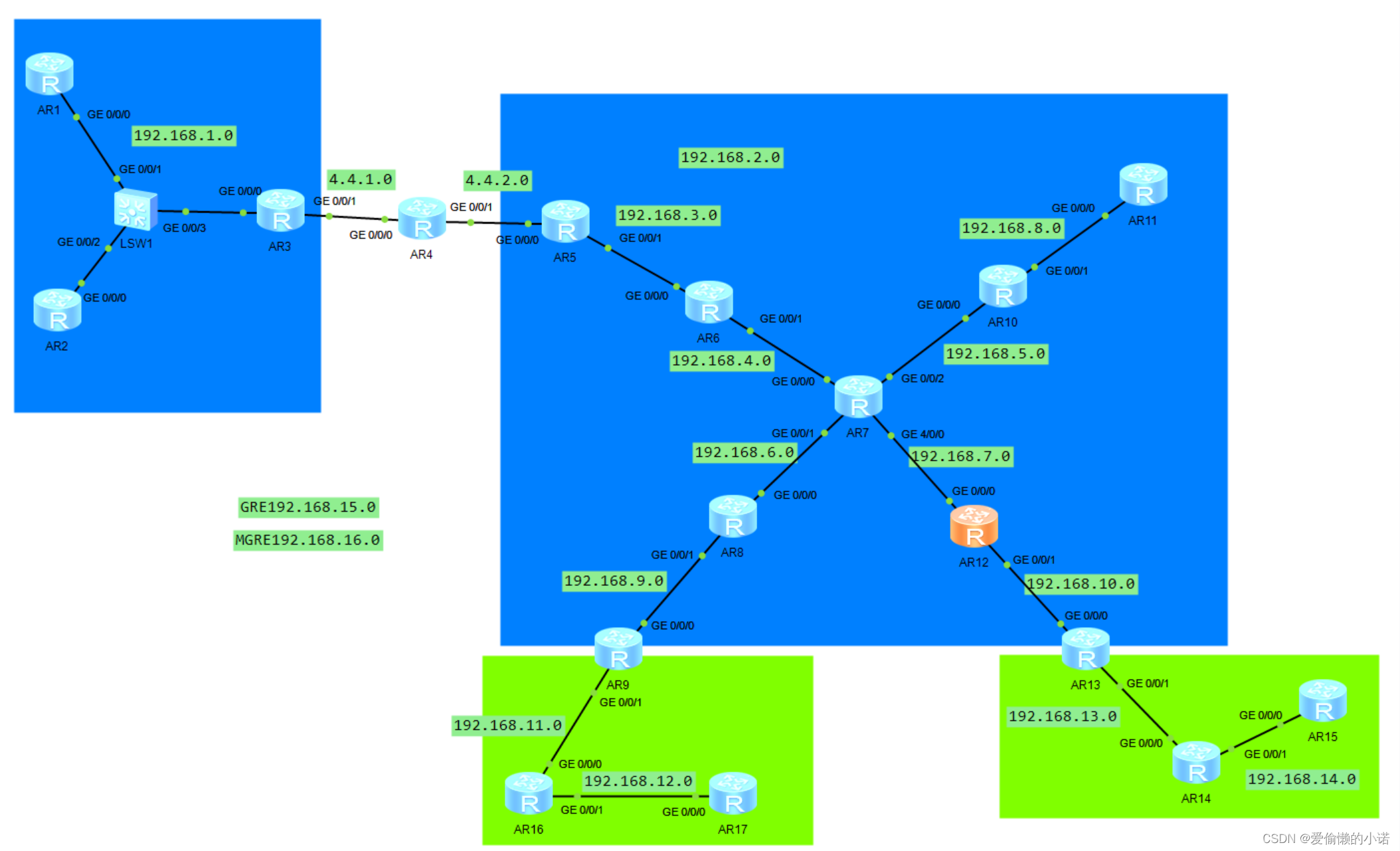
实验拓扑
实验要求:
1、左边三台设备配置OSPF 10,区域0;
2、右边为OSPF 1 中间是Area0,下挂Area1和Area2;
3、两个进程之间有ISP设备,需要访问公网。
4、OSPF 1区域零中,中心设备不启动动态路由协议,配置MGRE。
实验分析:
首先分配IP地址,在左边启动OSPF宣告,在R3上配置缺省,在R3在配置NAT
配置两条边界路由器指向ISP的缺省。
分别在各路由器(除R7)上启用OSPF
在R6\R8\R10\R12配置MGRE环境。
在除了ISP和R7的路由器上启用OSPF,按照要求宣告和选择区域。
在R3上配置GRE封装,对端为R5
[r3-Tunnel0/0/0]ip add 192.168.15.1 24
[r3-Tunnel0/0/0]tunnel-protocol gre
[r3-Tunnel0/0/0]source 4.4.1.1
[r3-Tunnel0/0/0]destination 4.4.2.2[r5-Tunnel0/0/0]ip add 192.168.15.2 24
[r5-Tunnel0/0/0]tunnel-protocol gre
[r5-Tunnel0/0/0]source 4.4.2.2
[r5-Tunnel0/0/0]destination 4.4.1.2
在R6、R8、R10、R12上配置MGRE环境
[r6-Tunnel0/0/0]tunnel-protocol gre p2mp
[r6-Tunnel0/0/0]source 192.168.4.2[r8-Tunnel0/0/0]tunnel-protocol gre p2mp
[r8-Tunnel0/0/0]source GigabitEthernet 0/0/0
[r8-Tunnel0/0/0]nhrp entry 192.168.16.1 192.168.4.1 register[r10-Tunnel0/0/0]tunnel-protocol gre p2mp
[r10-Tunnel0/0/0]source GigabitEthernet 0/0/0
[r10-Tunnel0/0/0]nhrp entry 192.168.16.1 192.168.4.1 register [r12-Tunnel0/0/0]tunnel-protocol gre p2mp
[r12-Tunnel0/0/0]source GigabitEthernet 0/0/0
[r12-Tunnel0/0/0]nhrp entry 192.168.16.1 192.168.4.1 register 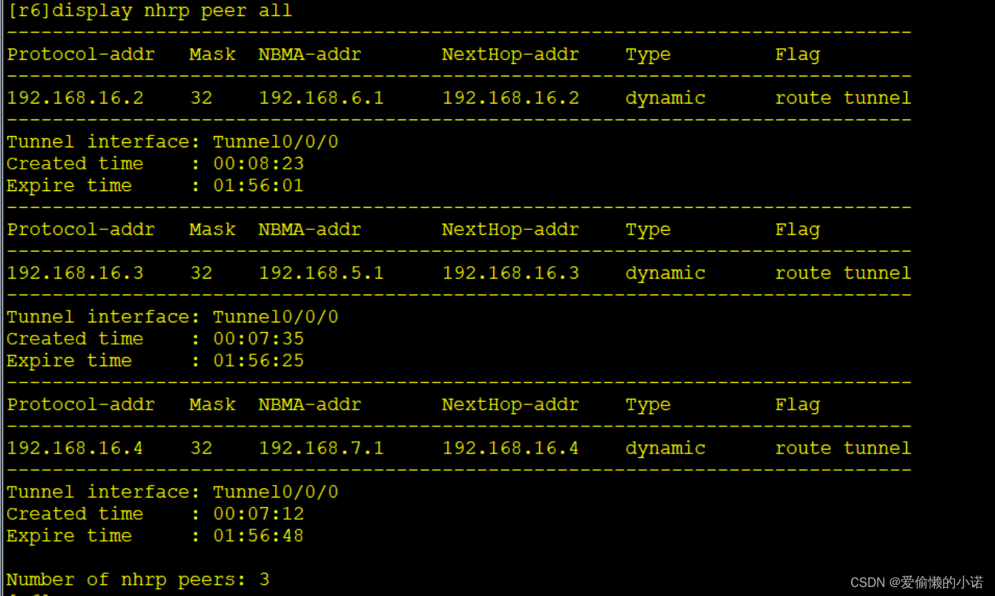
相关内容
热门资讯
人形机器人概念震荡调整,上纬新...
5月27日消息,人形机器人概念震荡调整,上纬新材跌近10%,大业股份、巨轮智能、德马科技、五洲新春、...
创新药概念局部活跃,艾德生物涨...
5月27日消息,创新药概念局部活跃,艾德生物涨超11%,昂利康涨超7%,泽璟制药、一品红、粤万年青、...
港股IPO动态:今日深演智能、...
5月27日消息,今日深演智能(2723.HK)、华曦达(0901.HK)、云英谷科技(3310.HK...
河南濮阳市濮阳县发生3.2级地...
5月27日消息,中国地震台网正式测定:05月27日00时46分在河南濮阳市濮阳县(北纬35.71度,...
前4月重点监测跨境电商进口平台...
5月27日消息,商务部发布数据显示,今年前4个月,重点监测跨境电商进口平台全球商品销售额增长4.3%...
日经225指数开盘涨1.20%...
5月27日消息,日经225指数开盘涨1.20%,报65777.87点;韩国综合股价指数(KOSPI)...
莲花控股:拟对阶跃星辰增资不超...
5月26日消息,莲花控股公告称,公司下属全资子公司莲花科创拟以现金增资形式对上海阶跃星辰智能科技股份...
*ST汇科:撤销退市风险警示及...
5月26日消息,*ST汇科公告称,公司撤销退市风险警示及其他风险警示的申请已获得深圳证券交易所审核同...
美股开盘:三大指数集体高开,太...
5月26日消息,美股三大指数集体高开,道指涨0.28%,纳指涨0.95%,标普500指数涨0.59%...
巴基斯坦国防部长:不会加入“亚...
5月26日消息,巴基斯坦国防部长赫瓦贾·阿西夫26日接受当地媒体采访时表示,巴基斯坦不会加入旨在推进...